Docker Reference Architecture: Docker Datacenter Best Practices and Design Considerations
Source:- docker.com
Introduction
Docker Datacenter (DDC) is the enterprise container platform from Docker to be used across the entire software supply chain. It is a fully-integrated solution for container-based application development, deployment, and management. With integrated end-to-end security, DDC enables application portability by abstracting your infrastructure so that applications can move seamlessly from development to production.
What You Will Learn
This reference architecture describes a standard, production-grade, Docker Datacenter deployment. It also details the components of DDC, how they work, how to automate deployments, how to manage users and teams, how to provide high availability for the platform, and how to manage the infrastructure.
Some environment-specific configuration details are not be provided. For instance, load balancers vary greatly between cloud platforms and on-premises infrastructure platform. For these types of components, general guidelines to environment-specific resources are provided.
Understanding Docker Datacenter Components
From development to production, Docker Datacenter provides a seamless platform for containerized applications both on-premises and on the Cloud. It includes three components:
- Docker CS Engine, the commercially supported Docker Engine
- Docker Trusted Registry (DTR), a resilient and secure image management repository
- Universal Control Plane (UCP), the web-based, unified cluster and application management solution
Together they provide an integrated solution with the following design goals:
- Agility — the Docker API is used to interface with the platform so that operational features do not slow down application delivery
- Portability — the platform abstracts details of the infrastructure for applications
- Control — the environment is secure by default, provides robust access control, and logging of all operations
To achieve these goals the platform must be resilient and highly available. This reference architecture demonstrates this robust configuration.
Docker CS Engine
The building block of Docker Datacenter, the Docker Commercially Supported Engine (CS Engine) is responsible for container-level operations, interaction with the OS, providing the Docker API, and running the Swarm cluster. The Engine is also the integration point for infrastructure, including the OS resources, networking, and storage.
Universal Control Plane
UCP extends CS Engine by providing an integrated application management platform. It is both the main interaction point for users and the integration point for applications. UCP runs an agent on all nodes in the cluster to monitor them and a set of services on the controller nodes. This includes identity services to manage users, Certificate Authorities (CA) for user and cluster PKI, the main controller providing the Web UI and API, data stores for UCP state, and a Classic Swarm service for backward compatibility.
Docker Trusted Registry
The DTR is an application managed by, and integrated with UCP, that provides Docker images distribution and security services. The DTR uses UCP’s identity services to provide Single Sign-On (SSO), and establish a mutual trust to integrate with its PKI. It runs as a set of services on one or several replicas: the registry to store and distribute images, an image signing service, a Web UI, an API, and data stores for image metadata and DTR state.
Swarm Mode
To provide a seamless cluster based on a number of nodes, DDC relies on CS Engine’s Swarm-mode capability. Swarm-mode divides nodes between workers, nodes running application workloads defined as services, and managers, nodes in charge of maintaining desired state, managing the cluster’s internal PKI, and providing an API. Managers can also run workloads, in a DDC environment they run UCP controllers, and shouldn’t run anything else.
The Swarm-mode service model provides a declarative desired state for workloads, scalable to a number of tasks (the service’s containers), accessible through a stable resolvable name, and optionally exposing an end-point. Exposed services are accessible from any node on a cluster-wide reserved port, reaching tasks through the routing mesh, a fast routing layer using high-performance switching in the Linux Kernel. This set of features enable internal and external discoverability for services, UCP’s HTTP Routing Mesh (HRM) adding hostname-to-service mapping.
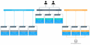
A Standard Deployment Architecture
This section demonstrates a standard, production-level architecture for Docker Datacenter using 10 nodes: 3 UCP controllers, 3 nodes for the DTR, and 4 worker nodes for application workloads. The number of worker nodes is arbitrary, most environments will have more depending on applications needs, it doesn’t change the architecture or the cluster configuration.
Access to the environment is done through 3 Load Balancers (or 3 load balancer virtual hosts) with corresponding DNS entries for the UCP controllers, the DTR replicas, and the applications running in the cluster.
The DTR replicas use shared storage for images. S3-compatible object storage (the default) and NFS storage are both covered in this section
Node Size
A node is a machine in the cluster (virtual or physical) with Docker Engine running on it. When provisioning each node, assign it a role: UCP Controller, DTR, or worker node so that they are protected from running application workloads.
To decide what size the node should be in terms of CPU, RAM, and storage resources, consider the following:
- All nodes should at least fulfil the minimal requirements, for UCP 2.0 2GB of RAM and 3GB of storage. More detailed requirements are in the UCP documentation.
- UCP Controller nodes should be provided with more than the minimal requirements, but won’t need much more if nothing else runs on them.
- Ideal Worker nodes size will vary based on your workloads, it is impossible to define a universal standard size.
- Other considerations like target density (average number of container per node), wether one standard node type or several are preferred, and other operational considerations might also influence sizing.
If possible, node size should be determined by experimentation and testing actual workloads, and they should be refined iteratively. A good starting point is to select a standard or default machine type in your environment and use this size only. If your standard machine type provides more resources than the UCP Controllers need, it makes sense to have a smaller node size for these. Whatever the starting choice, it’s important to monitoring resource usage and cost to improve the model.
Two example scenarios:
- One standard node size: 2VCPU, 8GB RAM, 20GB storage
- Two node sizes: 2VCPU, 8GB RAM, 20GB storage for UCP Controllers and 4VCPU, 64GB RAM, 40GB storage for worker nodes
Depending on your OS of choice, storage configuration for Docker Engine might require some planning. Refer to the Support Matrix to see what storage drivers are supported for your host OS. This is especially important if you are using RHEL or CentOS, which use device mapper with direct-lvm.
Load Balancers
Load balancers configuration should be done before installation, including the creation of DNS entries. Most load balancers should work with DDC. The only requirements are TCP passthrough and the ability to do healthchecks on an HTTPS endpoint.
In our example architecture, UCP controllers ensure UCP resiliency in case of node failure or controller reconfiguration. Access to UCP through the GUI or API is always done using TLS. The load balancer is configured for simple TCP pass-through on port 443, using a custom HTTPS health check at https://<ucp_controller>/_ping.
Be sure to create a DNS entry for the UCP host such as ucp.example.com and point to the load balancer.
The setup for the three DTR replicas is similar to setting up the UCP controllers. Again, use TCP pass-through to port 443 on the nodes, except the health check is at https://<dtr_replica_node>/health.
Create a DNS entry for the DTR host such as dtr.example.com and point it to the load balancer. It’s important to keep it as concise as possible because it will be part of the full name of images. For example, user_a‘s webserver image will be named dtr.example.com/user_a/webserver.
The application load balancer provides access to services HTTP endpoints exposed through UCP’s HTTP Routing Mesh (HRM). HRM provides a reverse-proxy to map domain names to services that expose ports and are attached to the ucp-hrm overlay network. As an example, the voting application exposes the vote service’s port 80. The HRM maps http://vote.apps.example.com to this port on the ucp-hrm overlay network, and the application LB itself maps *.apps.example.com to nodes in the cluster.
DTR Storage
The DTR usually needs to store a large number of images. It uses external storage (S3, NFS, etc.), not node storage so that it can be shared between DTR replicas. The DTR replicates metadata and configuration information between replicas, but not image layers themselves. To determine storage size, start with the size of the existing images used in the environment and evolve from there.
It’s best to use an existing storage solution in your environment so that image storage can benefit from existing operations experience. If you have to chose a new solution, consider using S3-compatible object storage, which maps more closely to registry operations.
Recommendations for the Docker Datacenter Installation
This section will detail the installation process for the architecture and provide a checklist. It is not a substitute for the documentation, which provides more details and is authoritative in any case. The goal is to help you define a repeatable (and ideally automated) process to deploy, configure, upgrade and expand your DDC environment.
The three main stages of a DDC installation are:
- Deploying and configuring the infrastructure (hosts, network, storage).
- Installing and configuring the Docker Engine, running as an application on the hosts.
- Installing and configuring UCP and the DTR, delivered as containers running on the engine.
Infrastructure Considerations
The installation documentation details infrastructure requirements for DDC. It is recommended to use existing or platform specific tools in your environment to provide standardized and repeatable configuration for infrastructure components.
Firewall
Access to DDC is done using port 443 only (ports 443 and 80 for DTR), whether it’s to access the Web UI or the remote API. This makes external firewall configuration simple. In most cases you only need to open ports 80, 443, and 22. Port 22 is for SSH access is is optional since DDC doesn’t require SSH access. Access to applications is through a load balancer using HTTPS. If you expose other TCP services to the outside world, open these ports on the firewall. As explained in the previous section, several ports need to be open for communication inside the cluster. If you have a firewall between some nodes in the cluster, for example, to separate controllers from worker nodes, open the relevant port there too.

Load Balancers
Load balancers are detailed in the previous section. They must be in place before installation and must be provisioned with the right hostnames. External (load balancer) hostnames are used for HA and also for TLS certificates. It’s easier not having to reconfigure them during or after installation.
Refer to the previous section DDC Components for details about load balancer configuration.
Shared Storage
DTR shared storage, used for images in the registry, must be ready and accessible from the DTR nodes. Test it works using an S3 or NFS command line client to avoid having to debug DTR storage configuration.
Host Configuration
Host configuration varies based on the OS used and existing configuration standards, but there are some important steps that must be followed after OS installation:
- Clock synchronization using NTP or similar service. Clock skew can produce hard to debug errors, especially where the Raft algorithm is used (UCP and the DTR).
- Static IPs are required for UCP for all hosts.
- Hostnames are used for node identification in the cluster. The hostname must be set in an non-ephemeral way.
- Host firewalls must allow intra-cluster traffic on all the ports specified in the installation docs.
- Storage must be configured if needed. For example, the
devicemapperdriver need a logical volume configured before Docker Engine installation.
Docker CS Engine Installation Considerations
Detailed installation instructions for CS Engine are provided by the documentation. To install on machines that don’t have Internet access, add these package to your own private repository. After installing the package, make sure the docker service is configured to start on system boot.
The best way to change parameters for CS Engine is to use the /etc/docker/daemon.json configuration file. This ensures that the configuration can be reused across different systems and OS in a consistent way. See the documentation for the full list of options.
Make sure Engine is configured correctly by starting the docker service and verifying the parameters with docker info.
UCP Installation Considerations
The UCP installer creates a functional cluster from a set of machines running CS Engine. That includes creating a Swarm cluster and installing the UCP controllers. The default installation mode as described in the Installation Guide is interactive.
To perform fully-automated, repeatable deployments, provide more information to the installer:
docker run --rm -v /var/run/docker.sock:/var/run/docker.sock \
  -v /tmp/docker_subscription.lic:/config/docker_subscription.lic \
  -e UCP_ADMIN_PASSWORD=password --name ucp docker/ucp install --host-address IP_or_interface \
  --san manager1.example.com --san ucp.example.com
Each of these options are explained in the following sections.
External Certificates
By default UCP uses self-signed TLS certificates. For production deployments, it is recommended to use certificates generated by a trusted CA. In most cases, this is your organization’s internal CA.
The certificates and keys needed as follows:
- The root CA’s public certificate
ca.pem. - The TLS certificate
cert.pem. It must also include the public certificates of any intermediate CA and have SANs for all addresses used to access UCP, including the load balancer’s hostname (e.g.ucp.example.com) and the individual controllers’ hostnames (e.g.ucp-controller1.example.com) to access them directly. - The TLS private key,
key.pem.
To add these automatically during installation, add these files with the exact names to a volume named ucp-controller-server-certs on the machine where you install UCP, and use the --external-server-cert install parameter.
It is also possible to add the certificates through the Web UI after installation.
License File
The license file can be provided for installation via the command line as well using a bind-mount (volume) in /config. Specify its location with -v /path/to/docker_subscription.lic:/config/docker_subscription.lic.
Admin Password
To make the installation entirely non-interactive, the admin password must be passed using the --admin-password install parameter. The admin username is admin by default. Use --admin-username to change it.
Adding Nodes
Once the installation has finished for the first controller node, the two additional controllers must be installed by joining them to the cluster. UCP configures a full controller replica on the manager node in the cluster, so the only command needed on the two controllers is a docker swarm join with the right token. The exact command can be obtained by running docker swarm join-token manager on the first controller.
To join the worker nodes, the equivalent command can be obtained with docker swarm join-token worker on any controller:
docker swarm join-token worker
To add a worker to this swarm, run the following command:
docker swarm join \
--token SWMTKN-1-00gqkzjo07dxcxb53qs4brml51vm6ca2e8fjnd6dds8lyn9ng1-092vhgjxz3jixvjf081sdge3p \
192.168.65.2:2377
To make sure everything is running correctly, log into UCP at https://ucp.example.com.
DTR Installation Considerations
Installation of the DTR is similar to that of UCP. Install and configure one node, and then join replicas to form a full, highly-available setup. For installation of the first instance as well as replicas, point the installer to the node in the cluster it will install on.
Certificates and image storage must be configured after installation. Once shared storage is configured, the two replicas can be added with the join command.
Validating the Deployment
When installation of everything has finished, tests can be done to validate the deployment. Disable scheduling of workloads on UCP controllers and nodes running the DTR.
Basic tests to consider:
- Log in through
https://ucp.example.comas well as directly to a manager node, eg.https://manager1.example.com. Make sure the cluster and all nodes are healthy. - Test that you can deploy an application following the example in the documentation.
- Test that users can download a bundle and connect to the cluster from the CLI. Test that they can use docker-compose.
- Test DTR with a full image workflow. Make sure storage isn’t misconfigured and images are stored in the right place.
Consider building a standard automated test suite to validate new environments and updates. Just testing standard functionality should hit most configuration issues. Make sure you run these tests with a non-admin user, the test user should have similar rights as users of the platform. Measuring time taken by each test can also pinpoint issues with underlying infrastructure configuration. Fully deploying an actual application from your organization should be part of this test suite.
High Availability in DDC
In a production environment, it is vital that critical services have minimal downtime. It is important to understand how high availability (HA) is achieved in UCP and the DTR, and what to do to when it fails. UCP and DTR use the same principles to provide HA, but UCP is more directly tied to Swarm’s features. The general principle is to have core services replicated in a cluster, which allows another node to take over when one fails. Load balancers make that transparent to the user by providing a stable hostname, independent of the actual node processing the request. It’s the underlying clustering mechanism that provides HA.
Swarm
The foundation of UCP HA is provided by Swarm, the clustering functionality of Docker Engine. As detailed in the Docker Engine documentation, there are two algorithms involved in managing a Swarm cluster: a Gossip protocol for worker nodes and the Raft consensus algorithm for managers. Gossip protocols are eventually consistent, which means that different parts of the cluster might have different versions of a value while new information spreads in the cluster (they are also called epidemic protocols because information spreads like a virus). This allows for very large scale cluster because it’s not necessary to wait for the whole cluster to agree on a value, while still allowing fast propagation of information to reach consistency in an acceptable time. Managers handle tasks that need to be based on highly consistent information because they need to make decisions based on global cluster and services state.
In practice, high consistency can be difficult to achieve without impeding availability because each write needs to be acknowledged by all participants, and a participant being unavailable or slow to respond will impact the whole cluster. This is explained by the CAP Theorem, which (to simplify) states that in the presence of partitions (P) in a distributed system, we have to chose between consistency (C) or availability (A). Consensus algorithms like Raft address this trade-off using a quorum: if a majority of participant agree on a value, it is good enough, the minority participant eventually get the new value. That means that a write needs only acknowledgement from 2 out of 3, 3 out of 5, or 4 out of 7 nodes.
Because of the way consensus works, an odd number of nodes is recommended when configuring Swarm. With 3 manager nodes in Swarm, the cluster can temporarily lose 1 and still have a functional cluster, with 5 you can lose 2, and so on. Conversely, you need 2 managers to acknowledge a write in a 3 manager cluster, but 3 with 5 managers, so more managers don’t provide more performance or scalability — you are actually replicating more data. Having 4 managers doesn’t add any benefits since you still can only lose 1 (majority is 3), and more data is replicated than with just 3. In practice, it is more fragile.
If you have 3 managers and lose 2, your cluster is non-functional. Existing services and containers keep running, but new requests are not processed. A single remaining manager in a cluster doesn’t “switch” to single manager mode. It is just a minority node. You also cannot just promote worker nodes to manager to regain quorum. The failed nodes are still members of the consensus group and need to come back online.
UCP
UCP runs a global service across all cluster nodes called ucp-agent. This agent installs a UCP controller on all Swarm manager nodes. There is a one-to-one correspondence between Swarm managers and UCP controllers, but they have different roles. Using its agent, UCP relies on Swarm for HA, but it also includes replicated data stores that rely on their own raft consensus groups that are distinct from Swarm: ucp-auth-store, a replicated database for identity management data, and ucp-kv, a replicated key-value store for UCP configuration data.
DTR
The DTR has a replication model that is similar to how UCP works, but it doesn’t synchronize with Swarm. It has one replicated component, its datastore, which might also have a lot of state to replicate at one time. It relies on raft consensus.
Both UCP controllers and DTR replicas may have a lot more state to replicate when (re)joining the cluster. Some reconfiguration operations can make a cluster member temporary unavailable. With 3 members, it’s good practice to wait for the one you reconfigured to get back in sync before reconfiguring a second one, or they could lose quorum. Temporary losses in quorum are easily recoverable, but it still means the cluster is in an unhealthy state. Monitoring the state of controllers to ensure the cluster doesn’t stay in that state is critical.
Backup and Restore
The HA setup using multiple nodes works well to provide continuous availability in the case of temporary failure, including planned node downtime for maintenance. For other cases, including the loss of the full cluster, permanent loss of quorum, and data loss due to storage faults, restoring from backup is necessary.
UCP Backup
UCP backup is done using the docker/ucp backup command on a controller node. It stops the UCP containers on the node and perform a full backup of the configuration and state of UCP. Some of this information is sensitive, so you should always use the --passphrase option to encrypt the backup. The backup also includes the orgs, teams, and users used by DTR as well as UCP. Regular backups should be scheduled. Here is an example showing how to run the command without user input:
UCPID=$(docker run --rm -i --name ucp -v /var/run/docker.sock:/var/run/docker.sock docker/ucp id)
docker run --rm -i --name ucp -v /var/run/docker.sock:/var/run/docker.sock docker/ucp backup --id $UCPID --passphrase "secret" > /tmp/backup.tar
There are two ways to use the backup:
- To restore a controller using the
docker/ucp restorecommand (only the backup from that controller can be used) - To install a new cluster using the
docker/ucp install --from-backupcommand (preserves users and configuration)
DTR Backup
A DTR backup includes configuration information, images metadata, and certificates. Images themselves need to be backed up separately directly from storage. Remember that users and organizations are managed and backed up by UCP.
The backup can only be used to create a new DTR, using the docker/dtr restore command.
Identity Management
Accessing resources (images, containers, volumes, networks etc) and functionality within the components of DDC (UCP & DTR) require at a minimum, an account and a corresponding password to be accessed. Accounts within DDC are identities stored within an internal database, but the source of creating those accounts and the associated access control can be manual (managed or internal) or external through a connection to a directory server (LDAP) or Active Directory (AD). Managing the authorization for these accounts is an extension of coarse and fine grained permissions that are described in the sections below.
Managed (Internal) Authentication
Managed mode of authentication and authorization is the default mode in DDC. In this mode, accounts are directly created using the DDC API. User accounts can be created manually by accessing the User Management —> Create User form in the UCP US. Accounts can also be created and managed in an automated fashion by making HTTP requests to the authentication and authorization RESTful service known as eNZi.
User management using the “Managed” mode is recommended only for demo purposes or where the number of users needing to access DDC is very small.
Pros:
- Easy and quick to setup – Simple to troubleshoot
- Appropriate for a small set of users with static roles
- Managed without leaving the UCP interface
Cons:
- User Account management gets cumbersome for larger numbers or when roles need to be managed for several applications.
- All lifecycle changes such as adding / removing permissions of users need to be accomplished manually user by user.
- Users must be deleted manually, meaning access may not get cleaned up quickly, making the system less secure.
- Sophisticated setups of integrating application creation and deployment through LDAP or external systems is not possible.
LDAP / AD Integration
The LDAP method of user account authentication can be turned on to manage user access. As the name suggests, this mode enables automatically synchronization of user accounts from a directory server such as Active Directory or OpenLDAP.
This method is particularly applicable for enterprise use cases where organizations have a large set of users, typically maintained in a centralized identity store that manages both authentication and authorization. Most of these stores are based on a directory server such as Microsoft’s Active Directory or a system that supports the LDAP protocol. Additionally, such enterprises already have mature processes for on-boarding, off-boarding, and managing the lifecycle of changes to user and system accounts. All these can be leveraged to provide a seamless and efficient process of access control within DDC.
Pros:
- Ability to leverage already established access control processes to grant and revoke permissions.
- Ability to continue managing users and permissions from a centralized system based on LDAP.
- Increased security due to self-cleaning nature of this mode, where non-existent LDAP users are automatically removed from DDC on the next sync.
- Ability to configure complex upstream systems such as flat files, database tables using an LDAP proxy, and the automatic time-based de-provisioning of access through AD/LDAP groups.
Cons:
- Increased complexity compared to Managed mode
- Higher admin requirements since knowledge on an external system (LDAP) is needed
- Greater time needed to troubleshoot issues with an extra components (LDAP) in the mix
- Unexpected changes to DDC due to changes made to upstream LDAP/AD systems, which can have unexpected effects on DDC
A recommended best practice is to use group membership to control access of users accounts to resources. Ideally, the management of such group membership is achieved through a centralized Identity Management or a Role Based Access Control system. This provides a standard, flexible, and scalable model to control the authentication and authorization rules within DDC through a centralized directory server. Through the Identity Management system, this directory server is kept in sync with user on-boarding, off-boarding, and changes in roles and responsibilities.
To change the mode of authentication, use the form at Admin Settings —> Auth in the UCP UI. In this form, change the METHOD field under Authentication from the default value of Managed to LDAP.
Accounts that are discovered and subsequently synced from the directory server can be automatically assigned default permissions. It is recommended to leave the option for default permission to No Access Any necessary additional access can be granted based on group memberships.

For details about the LDAP configuration options, read the Integrate with LDAP documentation.
This section highlights important configuration options to consider when setting up LDAP authentication.
In LDAP auth mode, when accounts are discovered and subsequently imported, all previously created accounts in a Managed mode including the admin accounts are deleted. A new admin account is created when authentication is switched to LDAP. This admin account is a local account and is intended to be useable independent of the LDAP settings (for example, in a situation when there is a loss of connectivity to the directory server). The details of this admin account can be set during the sync using RECOVERY ADMIN USERNAME and RECOVERY ADMIN PASSWORD.
A user account on the directory server has to be configured to discover and import accounts from the directory server. This user account need not be a very powerful account. In fact, it is recommended that it is a read-only account that can view the necessary organizationalUnits (ou) and query for group memberships. The details for this account are configured using the fields READER DN and READER PASSWORD. The READER DN must be in the distinguishedName format.
Use secure LDAP if at all possible.
Use the Test LDAP Connection section to make sure you can connect before switching to LDAP authentication.
Once the form is filled out and the test connection succeeds, the sync button provides an option to run a sync immediately without waiting for the next interval. Doing so initiates an LDAP connection and runs the filters to import the users. Any previously logged in user is logged out due to the disablement of all pre-existing accounts.

After the sync is complete, it should be possible to log in using the recovery account and password. Be sure to test this recovery account. It should also be possible to log in using a sync-ed LDAP/AD account (the only supported attributes are uid and sAMAccountName) and its corresponding LDAP/AD password. The sync-ed account should be in good standing within the LDAP/AD system for the login to be successful within DDC.
The progress / status of the sync and any errors that occur can be viewed and analyzed on the controllers by running:
docker logs ucp-controller
Teams
User accounts that exist within DDC, either through an LDAP sync or manually managed, can be organized into teams. Each team created can be assigned customized permissions and managed as a group of users as opposed to granting permissions to each user account on an individual basis.
Teams can be created in the UCP UI using the TEAMS +Create interface under User Management. The same can be accomplished by using the eNZi API that is described in a later section. Members can be added to the team one-by-one. An alternative method of adding members to a team can be employed if using the LDAP Auth mode. This is based on an automatic sync of discovered accounts from the directory server that was configured to enable the LDAP Auth mode. Finer filters can be applied here which determine which discovered accounts are placed into which teams. A team can have multiple users, and a user can be a member of zero to multiple teams.
RBAC and Managing Team Level Access to Resources
Permissions to resources through UCP are managed through default access levels. The default access permissions are No Access, View Only, Restricted Control and Full Control. Description about these permissions and how they relate to each other are detailed in the Reference Architecture Securing Docker Datacenter and Security Best Practices. These permissions can be further extended by adding the user accounts to specific teams. In other words, the default permissions assigned directly to a user provide a coarse-grained access control. The user should then be added to teams to attain higher granularity in what a user account can do on specific containers, images, and other resources. The teams are assigned attributes in the form of labels that provide additional flexibility through a fine-grained access control. In some ways this mimics a traditional Role Based Access Control (RBAC), where the teams are the roles assigned to user accounts, but there are specks of the finer Attribute Based Access Control (ABAC) through the assignment of one of more labels to each team, which ultimately define the level of access of the account to UCP resources.
While teams can be associated with as many labels as necessary, the resources within UCP like services, images, volumes, networks, and secrets can also be associated with any one of these labels to tie the two together. It should be noted that any labels assigned to a service are automatically inherited by the tasks which currently are container workloads. So this behaves in just the same way as assigning meta information in the form of labels to containers (or any other resource for that matter). Internally, the resources are assigned a label with the key com.docker.ucp.access.label with the value as specified.
It would be easier to understand with a concrete example as described in the following section.
Strategy for Using LDAP Filters
This section demonstrates a typical use case that uses the principles of “least privilege / permission” as well as “separation of duties.”
Suppose you have a simple application called www, which is a web server based on the nginx official image. Say there are three teams that need access to this application — developers, testers, and operations. Typically, testers need View Only access and nothing further, while the operations team usually needs Full Control. The developers team needs access to troubleshoot, restart, and control the lifecycle of the application but should be forbidden from any other activity involving the need to access the host file systems, or starting up privileged containers. This type of special access is termed Restricted Control.
The users needing to access UCP are all sourced from the corporate Directory Server system. These users are the admin users needed to manage DDC infrastructure as well as all members of each of the teams configured within UCP. Also assume that the total universe of users needing access to DDC (includes admins, developers, testers and operations) is a subset of the gamut of users within the Directory Server.
A recommended strategy to use when organizing the DDC users is to create an overarching membership group that identifies all users of DDC irrespective of which team they are a part of. Let us call this group DDC_Users. No user should be made a member of this group directly. Instead, the DDC_Users group should have other groups in it and only groups as its members. Per our example, let us call these groups dev, test, and ops. In our example, these groups are part of what is known as a nested group structure within the directory server. Nested groups allow the inheritance of permissions from one group to each of its sub-groups.
**NOTE:** Some directory servers do not support the feature of nested groups or even the `memberOf` attribute by default. If so, then they would need to be enabled. If the choice of directory server does not support these features at all, then alternate means of organizing users and querying them should be used. Microsoft Active Directory supports both these features out of the box.
User accounts should be added as members of these sub-groups in the directory server. This should not impact any existing layout in the organization units or pre-existing group membership for these users.
Within UCP, the first step is to enable the LDAP Auth mode. Under User Search Configurations, for the FILTER field, the value based on our example above should be (&(objectClass=person)(memberOf=cn=DDC_Users,ou=groups,dc=example,dc=com)).
Performing a sync with this setting discovers and import all users that are members of the group DDC_Users (through the nested sub-groups).
Next, using the TEAMS +Create link under User Management, the individual teams can be created. An example of creating the developers team is shown below. The value of the Group DN field reflects the sub-group created under DDC_Users called dev.

After the team is created, bring up the Add Label form by clicking on the PERMISSIONS link. Here, as many permissions as needed can be added. In the image below, two labels are added to denote that members of the developers team have View Only access to any resource labeled as production. An additional label grants the members of the developers team Full Control on resources labeled as development.

Similarly, the testers and operations teams are created and assigned permissions per the table below:
| Team | Group | Permissions |
|---|---|---|
testers |
cn=test,ou=groups,dc=example,dc=com |
production: No Access |
development: View Only |
||
operations |
cn=ops,ou=groups,dc=example,dc=com |
production: Full Control |
development: Full Control |
Now, you can create the service www and assign it the appropriate access label to allow only specific users access to the resource using a command like below:
docker service create --name www -p 80:80 --label com.docker.ucp.access.label=development nginx
The same can be done in the UCP UI while creating a service by selecting an appropriate label (development in this example) from the PERMISSIONS LABEL dropdown as shown below. The label is applied to the service for enforcing role-based access control.

Only those labels that the logged in user has access to shows up in the dropdown. An admin user or a user assigned Full Control permission is shown all available labels regardless of the labels assigned to the team of which the user is a member of.
Now, create another service www-prod similarly based on the nginx image but with the Permission Label of production applied to it while logged in as a user boyle who is a member of the developers team. His permissions look as follows:

The account boyle can see both services, www and www-prod, but only the www service allows edits and other control because the permission label of development matches with the team’s resource label of development granted with Full Control permissions. The www-prod service forbids any edits using the account boyle because it has a permission label of production, which has been marked as View Only in the team developers' resource label. For example, if the account boyle was used to scale up the number of replicas of each service, from 1 to 2 (for instance), an error of Access Denied would be thrown for the www-prod service, while the same would work for www service.
Further, as evident in the profile image, boyle has Default Permissions of No Access. This prevents the boyle account from accessing any other resource unless the permission label and team resource label match and provide explicit permissions that override the No Access default permission.
Finally, if and when it becomes necessary to terminate all access for any user account, removing the group membership of the account from just the one group DDC_Users would remove all access for the user. Due to the nature of how nested groups work, all additional access within DDC is automatically cleaned — the user account is removed from any and all team memberships at the time of the next sync without need for manual intervention or additional steps. This step can be integrated into a standard on-boarding / off-boarding automated provisioning step within a corporate Identity Management system.
Authentication API (eNZi)
The AuthN API or eNZi (as it is known internally and pronounced N-Z) is a centralized authentication and authorization service and framework for DDC. This API is completely integrated and configured into DDC and works seamlessly with UCP as well as DTR. This is the component and service under the hood that manages accounts, teams and organizations, user sessions, permissions and access control through labels, Single-Sign-On (Web SSO) through OpenID Connect, and synchronization of account details from an external LDAP-based system into DDC.
For regular day-to-day activities, users and operators need not be concerned with the AuthN API and how it works, however its features can be leveraged to automate many common functions and/or bypass the DDC UI altogether to manage and manipulate the data directly.
The RESTFul AuthN API endpoints are documented in the AuthN API.
Interaction with AuthN can be accomplished in two ways: via the exposed RESTful AuthN API over HTTP or via the enzi command.
For example, the command below uses curl and jq to fetch all user accounts in DDC via the AuthN API over HTTP:
curl --silent --insecure --header "Authorization: Bearer $(curl --silent --insecure \
     --data '{"username":"<admin-username>","password":"<admin-password>"}' \
    https://<UCP-domain-name>/auth/login | jq --raw-output .auth_token)" \
    https://<UCP-domain-name>/enzi/v0/accounts | jq .
The AuthN service can also be invoked on the CLI on a UCP controller. To connect into it, run the following on a UCP controller:
docker exec -it ucp-auth-api sh
At the resulting prompt (#), type the enzi command with a sub-command such as the one below to list the database table status:
enzi db-status